HELICOPTER ARTICLES: written by various authors :
Operational considerations for a co-axial, contra-rotating rotor.by: ZED H
submitted: 01 Jan 2001
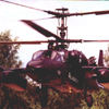
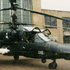
In the consideration of the possible advantages and/or disadvantages it is of interest to look this and similar designs. Kamov has a long history of contra-rotating rotor configurations and hence has a great heratge on which to build such platforms. Kaman displaces each rotor off to either side of the aircraft longitudinal axis, having geared the rotor blades to effectively intermesh, while the Chinook has it rotors displaced at the extemities of the aircraft. The co-axial configuration can be seen to have reduced package size over differential positioning of rotors. Some of the advantages & dis-advantages are listed below.
 Advantages:
No tail rotor
-
-
- No shaft to be vulnerable. Tail rotor shaft failure remains one of the prime causes of helicopter accidents, both military and civilian. In the absence of any tail rotor to drive, this one problem area is removed as the long, normally highly stressed (as the initial test of the Mi-28 showed) shaft proves very vulnerable to battle damage, due mainly to the necessity for weight reduction.
- No drive train losses due to tail rotor. While the drive train/gearbox required for a contra-rotating lay out is considerably larger than that of a conventional helicopter, it is still smaller, and hence subject to lower mechanical losses, than a that of a conventional helicopter’s gearbox and additional tail rotor drive gears. Additional losses for conventional helicopters would even go as far as power losses due to the additional pumping of oil services out to the tail rotor gearbox on some helicopters.
- Shorter fuselage, smaller helicopter, reduction of visual signature, smaller target. A great benefit of this sort of helicopter layout is that of the small size of the operational aircraft’s considerably shorter fuselage. In addition to this the stowed aircraft will take up considerably less hanger/bunker space compared to most of their contemporizes (as with the other members of the maritime Kamov family, the Ka-50/52 is equipped with folding rotor-blades).
- No possibility of tail rotor strike; a major cause of helicopter crash. With the exclusion of the tail rotor a major cause of helicopter accidents has also been reduced; with an absence of the possibility of a tail rotor strike, pilots can have more confidence to get down low and allow themselves to be lost in ground clutter (an important factor for a combat helicopter).
- Reduced audio signature. A tail rotor has the problem of, due to its small size, high rotational speed and subsequently operated close to the transonic region. This has the effect of producing a great deal of noise, as under certain conditions, the tips can go sonic, producing the accompanying ‘boom’.
- Reduced angular momentum. Without the need for that tail rotor, and the subsequent reduction in fuselage length, angular momentum is lower as there is no large mass hanging way out to the rear. The effect this has on aircraft capability is that faster, more accurate turns can be accomplished.
- Higher speed possible due to no RBS on tail rotor, increase high-speed directional stability. As this particular rotor layout is not subject to the dynamic roll that conventional rotor configurations a subject to, control authority in a given direction does not reduce with speed. This allows for a wider operational envelope than would be otherwise possible. Given this additional control authority available, higher speeds are attainable (also as a function of the absence of a tail rotor and it not suffering RBS).
 Co-axial rotor
-
-
- Directional stability through cancellation of main rotor gear torque moment (torque reaction). As each rotor disc rotating in the opposite direction, hence cancelling any torque reaction on the fuselage and allowing for directional stability by not having to counter this reaction by applying rudder as collective is increased.
- Indifference to cross wind conditions; reduction in operational height, higher tracking accuracy. The rotor configuration is not effected by crosswinds due to the absence of loss of tail rotor effectiveness. As air blows through the tail rotor in the direction it is blowing air, efficiency is lost and the rotor pitch needs to be increased (possibly leading to a tail rotor stall). This indifference, coupled with the absence of a tail rotor, allows for ultra-low level operations around obstacles. If a target is being tracked with a weapons platform (say, rockets) this will allow higher efficiencies to be achieved, by reducing the level of correction needed due to gusts during the track.
- No dynamic roll. Dynamic roll, seen prior to the onset RBS (which would still incur a pitch-up) is effectively eliminated due to the balance of the differential lift effect from the different sides each of the rotor discs.
- Increased pressure differential over rotor system; increased thrust; higher efficiency for increase in thrust, reduction in rotor diameter for given thrust. This combination shows a greater efficiency in increase in thrust per unit increase in power. It is both dimensionally more compact and aerodynamically more efficient that that of a conventional rotor layout.
- Compact size through use of concentric shafts. With use of a concentric contra-rotating shaft, the size of the system can be made smaller that that of other contra-rotating systems.
- High level of yaw authority, extending well into the flight envelope. As yaw authority is not totally limited to that of the aerodynamic capabilities of a tail rotor, being dependant on that of the differential rotational inertia applied to each disc, being used to generate a yawing motion, operability extends beyond that of the tail rotor system.
 Disadvantages:
Operation/design complexity
-
-
- Complexity of linkages required to operate pitching control for each of the rotor systems and the problems of maintenance there with. The nature of very complex linkages results in greatly complex manufacture, assembly and susceptibility to battle damage. This has costing implication for manufacture time and man-hours for assembly. -
- Issue of maintenance access necessitating disassembly of large portions of main rotor gear to replace e.g. battle-damaged components. The complexity and level of articulation of components results in high maintenance time, lubrication issues for articulation and contact points. Lower level of redundancy due to failure of one point on articulated component resulting in component inoperability (failure) during operation. The co-axial configuration may require that one or both the rotor drive/shaft systems requiring disassembly to access areas where battle damage has grounded it. -
- Inter-disc wash interference. Increase in audio signature. Alpha considerations for lower disc. Reduce efficiency of lower disc. As far as theory goes there is are strict restriction for the alpha limits on the lower disc due to the swirl imparted to the downwash flow from the upper disc. Hence the upper swirls the air in the opposite direction to which the disc rotates, this will result in the flow travelling in the same direction as the lower disc. Low disc has to run faster to allow it to generate the same lift as the upper rotor. This results in high tip speed on lower disc resulting in the normal decrease in efficency, increase in noise etc. The real issues lies in the fact that part of the lower may be running at a lower aerodynamic incidence than its physic incidence if equal physical incidence is used on the upper and lower disc (effecively resulting in negative lift). This results in a requirement to run the lower disc at far higher physical incidence than the upper. This is just considering the hover; once moving the whole problem becomes far more non-linear and hence the design complexity increases. (basically a - 'don't try this at home kids') -
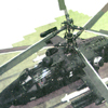
- Importance of flow interaction, requirement for disc spacing. There will be restrictions over inter-disc spacing due to purely aerodynamic considerations. In the case of contra-rotating propeller blades, spacing is not a great aerodynamic issue as any cross-wind component will be disproportionally small in comparision to the axial flow due to the direction of flight. In the case of a helicopter (especially at high speed), this will not be an component that can be ignored. To ensure sufficently clean flow for the lower disc, the spacing must be wide enough to allow as little interaction of the swirl of the upper rotor to impinge on the retreating component of the lower disc. This must be such that the design tollerence for blade incidence is not exceeded anywhere over the lower disc. Hence another consideration for the increase in the lenght of the rotor head. -
- Additional weight and complexity of main gear drive. To drive a contra-rotating configuration takes much more robust drive gear over, say, the gearing to drive the tail rotor, although losses would be comparable, due to the two boxes required for the tail rotor. In addition to this a co-axial nature, requires the gearing all to be confined to within a relatively small space to gear both shafts, from both engines. Compactness also introduces cooling problems, due to the density of mechanics that require lubrication. -
- High cost. The nature of this rather unusual configuration results in a relatively high cost (dependant on cost per man-hour per unit produced, so in the FSU where man-time, and manufacture-cost is low, so is unit cost, but not for the US). Hence higher running cost due to longer maintenance time and higher component cost.
 Flight restrictions
-
-
- Restrictions on operation during high speed and certain manoeuvring conditions in flight envelope. G restriction for blade contact due to phase lag of differential rotor set-up. Due to the nature of the phase lag, running in opposite directions the lag will manifest itself at different times on either disc. The problems that this will cause are related to that of a non-uniform distance being maintained between the two rotor-discs. If we consider a condition under harsh, high [rotor] G manoeuvring [positive], where the discs are operating in close proximity to their lift limit, as this level the coning angle for the disc drops inconsistantly. If the upper drops harshly, say at stall, it will take up a near zero degree coning angle, while the lower may be operating at a maximum level of lift, will be operating at its maximum coning angle. In addition to this, under such high G conditions, the flexural nature of the rotor blade could increase the likelihood of inter-disc contact. Under very high G loads and harsh manoeuvring the level of blade rigidity required to withstand a condition of blade contact is large. Another condition where contact can occur is a high rate yaw, while at slow speed or in a hover. This condition exemplifies the level of lift on one rotor to compensate the loss of lift on the other. This has a similar effect on the cone angle as described above, where blade angles on the lower disc are high and those of the upper disc are low. [This condition actually occurred on a Ka-50 at low level, resulting in the loss of the pilot, but restrictors have been introduced to alleviate this problem.] -
- Blade contact during RBS. During an RBS condition, the phase lag of both discs cause the stall area to fall in different angular positions in relation to the centreline. During this condition the growing stall area at the rear which results in lift loss at the rear of the disc causing the disc the rapidly pitch up. As the discs fall at the rear in different positions (and being subject to a high level of vibration), blade contact becomes increasingly likely. -
- Issues of stability of main rotor shaft due to length. (Rosette resonance?). When any shaft rotates, it is subject to transverse oscillations down the length of the shaft. When viewed from above [over a length of time] the shaft will prescribe a rosette. This rosette will increase or decrease depending on the level of resonance that the shaft is subject to. Now, given that the length of the shaft required for a co-axial layout is usually long in comparison to that of a conventional layout, this greatly reduces the frequency at which resonance would occur. Given that contra-rotating layout is useful in counter-balancing cyclic forces on the rotor shaft, this would appear not to be a problem. But due to manufacturing tolerances, this will never be perfectly balanced, and given the forces possible higher frequency (given battle damage or poor manufacturing or RBS conditions), the fact that the shaft length brings resonance frequency down and this forces frequency increases in these conditions, a possibility of coincidence could occur resulting in resonance. Active cancellation techniques do go a long way the reducing this, but as can be seen here this is an incentive for shortening that shaft. -
- Much higher rotor drag. Function of aerodynamic and aero-elastic consideration resulting in high inter-disc spacing. Higher fuel consumption/reduced range. The height & bulk of the rotor gear results in a high drag over that of a conventional configuration. This is the result of the requirement to minimise the conditions above, taking into consideration the aerodynamic and aeroelastic properties of this configuration. A compromise must be struck, therefore, between the probability of a given blade contact condition (increase spacing required) and the induced drag of the rotor head (reduced spacing required). As a result of the higher drag, maximum sustained speed per unit power input into the rotor system, can be lower than for a conventional layout, but given clever aerodynamics may exceed this, given the greater level of thrust produced by the dual rotor. This would increase the development time in perfecting this compromise (given limited previous experience). High drag will also have the effect of higher fuel consumption at speed, and as a consequence lower max range speed, and therefore lower range. [The height of the rotor could also result in a higher frontal visual signature on the battlefield, during non-masked attacks.]